
Abstract
To evaluate the efficiency of ground-penetrating radar (GPR) to map root systems of urban trees in situ, this technique was tested on three trees in an urban environment. After carrying out the extremely rapid GPR tests around the bases of the sample trees, root systems were excavated with an air spade, which produces a supersonic jet of air used to remove soil from roots. Photographs were taken of root system transects for comparison with GPR images. Root system architecture was then quantified for one pine tree, and a two-dimensional image of the root system was reconstructed using AMAPmod software. A comparison of actual roots with images hand drawn from the GPR data showed that the technique is reliable for mapping large roots in the horizontal plane only. Most errors in data from the GPR method were induced when the root systems were manually redrawn, and from roots running parallel to the electromagnetic signal in the vertical plane. These roots could not be identified by GPR. The GPR technique could be considered a valuable nondestructive tool for the arborist, but it still needs development, especially with regard to a software that could reconstruct 3D images of root system architecture from raw data.
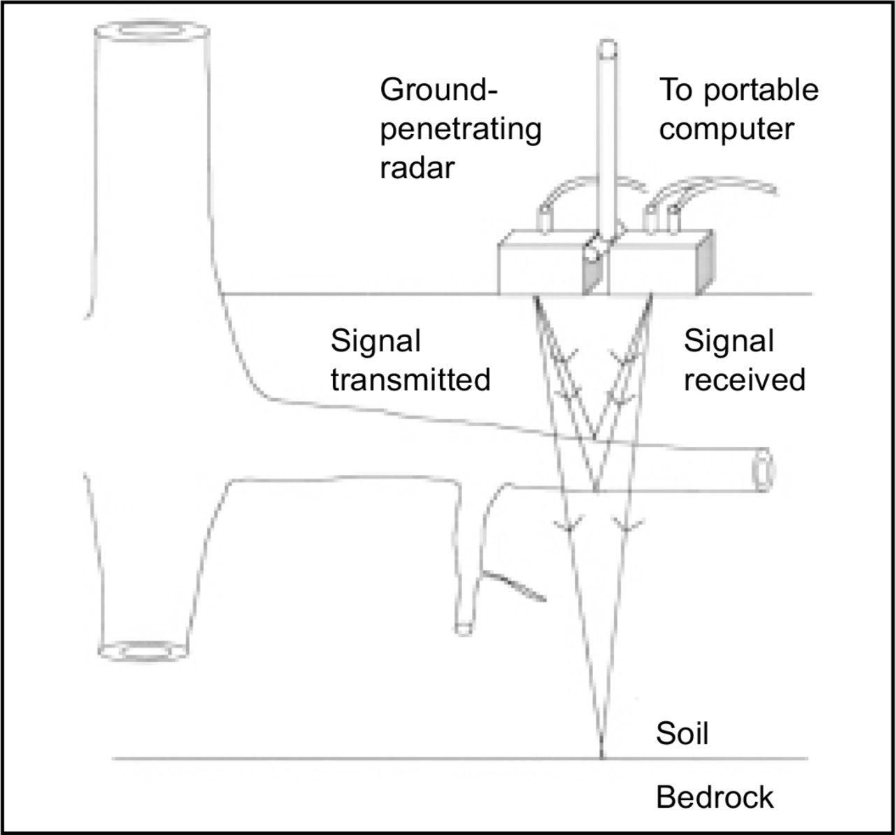
Tree root systems are often considered a major threat to certain structures in urban environments, especially when growing near building foundations and underground utilities such as gas or sewage pipes (Cermak et al. 1997). Insurance companies are subject to increasing numbers of claims from householders and private firms whose buildings allegedly suffer subsidence or structural damage from nearby street trees. However, an efficient and inexpensive method does not yet exist for mapping tree root systems or for identifying the presence of individual large roots. A recent study examined a new nondestructive technique, X-ray computed tomography (Pierret et al. 1999), but this technique is far from being practical enough to be used by the arborist. Using existing and new technology, as well as knowledge from different scientific disciplines, this paper describes a pilot study to investigate the reliability of one nondestructive method, georadar, for determining the position of individual roots, as well as the architecture of tree root systems in situ in an urban environment. Ground-penetrating radar (georadar, GPR) projects high-frequency impulses of energy into the soil from a portable radar system. Energy is reflected back to the surface when the impulse strikes an interface between soil particles (Figure 1). This reflected energy is then recorded on a portable computer. The primary use of GPR has been the identification of compacted soil horizons, stone lines, bedrock, and water tables in soil surveys (Doolittle 1987).The GPR technique is also used by archaeologists for locating buried artifacts. Some of these archaeologists claim that tree roots can also be identified in their GPR images (Cammarano and Piro 1997; Papamarinopoulos et al 1997).

Schematic representation of a portable ground-penetrating radar (GPR) device. Tree roots are detected by an electromagnetic signal, as anomalies in the soil, and this information is transmitted in the form of travel time pulses to a portable computer.
Although mapping tree root systems with GPR has been successfully used and tested in forest and woodland environments, where soil is relatively homogenous (Hruska et al. 1999; Sustek et al. 1999), doubts still exist about the accuracy of this technique in an urban environment. In towns and cities, soil can be extremely heterogeneous and often contains pipes and cables that interfere with signal processing. This method has been used in an urban environment, although not verified by root excavation (Cermak et al. 2000). Several researchers have also tested this technique, although without much success (C. Lohou, pers. comm.; B.C. Nicoll, pers. comm.). These researchers both stated that the main problem with GPR is that it is not possible to tell the difference between underground pipes and stones from roots. However, Hruska et al. (1999) claim that their GPR system has a very high resolution and can even distinguish between water-filled pipes and tree roots.
In this study, the reliability of the GPR technique was tested on urban trees, which were subsequently excavated using an air spade (Rizzo and Gross 2000). Root architecture was then measured and manually digitized (Danjon et al. 1999a, 1999b) to compare two-dimensional root system images with those created by the GPR data.
MATERIALS AND METHODS
Experimental Site and Sample Trees
The experimental site was situated in a garden in the city of Brno, Czech Republic [latitude 49°12’, longitude 16°39’, altitude 225 m (738 ft)] on a slight (5%) west-facing slope. The site was characterized by a hard and deep loessclay soil of quaternary origin with a 20% mixture of gravel, covered in places by a shallow layer of lighter soil, mixed with bricks and construction rubble (Cermak et al. 2000). Subsoil was composed of sediments of tertiary origin, Pleistocene loess, torton calcareous clays of montmorilonite type with local occurrence of oncoforous sands (Janovsky 1996). Recent climatic data (monthly means from 1991 through 1996) showed prevailing dry weather in late summer months (Hydrometeorological Institute, Brno).
Three trees were chosen for the evaluation of GPR. One solitary pine (Pinus nigra Arn.) and two mountain ash (Sorbus intermedia (Ehrh.) Pers.) trees, which were growing at distances of 6 and 20 m (19.7 and 65.7 ft), respectively, from the edge of a 2-m-deep (6.6-ft) ditch, where a large two storey building was situated. The two mountain ash trees were growing at a distance of 2.7 m (8.9 ft) from each other, and thus had interlocking crowns. The smaller mountain ash tree had been damaged by the removal of a 20-cm-wide (7.9-in.) strip of bark along the stem on the east side, resulting in a wound infected by a saprophytic fungus (Exidia glandulosa, Phragmobasidiomycetes).
Ground-Penetrating Radar
Ground-penetrating radar (GPR) measurements were carried out on root systems using the same method used in previous studies (Hruska et al. 1999; Cermak et al. 2000). The trees were surrounded by a 6 × 6 m (64.6 × 64.6 ft) plot of grass around the pine tree, and a 9 × 7 m (96.9 × 75.3 ft) plot around the two mountain ash trees. There was a small stump from a shrub growing in the southeast corner of the examined area around the pine, and two other smaller mountain ash trees and one lime (Tilia platyphyllos) tree were growing near the southern edge of the area to be measured around the mountain ash trees. Two small shrubs were also situated close to the northeastern edge of this sampling area. It could therefore be presumed that the GPR signals would detect not only roots of the sample trees but also roots from nearby trees and woody shrubs. This mixture of roots was not an ideal situation for testing GPR on urban tree roots, but it was not possible to find isolated trees whose root systems could be excavated and which could be felled after the experiment.
GPR measurement was performed with a portable signal transmitter and receiver-type pulseEKKO 1000A™ GPR system (Sensors & Software Inc., Mississauga, Ontario) using a signal frequency of 450 MHz, which allows horizontal as well as vertical distances to be distinguished with a precision of 5 cm (2 in.). Roots with a diameter greater than 2 cm (0.8 in.) can be identified down to a depth of 2.5 m (8.2 ft). The instrument was gradually moved over the soil surface along specified grid lines, and vertical “slices” of soil were measured (Figure 1). The profile step was 0.05 m (0.2 ft) along lines 0.25 m (0.8 ft) apart in two perpendicular directions. In total, 301 m (987 ft) of lines were scanned, giving 6,160 records for pine, and 476 m (1,562 ft) with 9,504 records for the two mountain ash trees together.
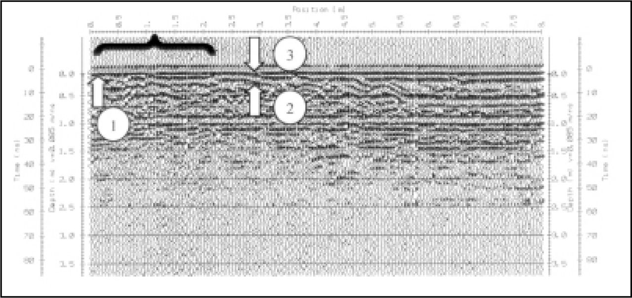
The effective velocity needed to transfer the radar signal into the soil was v = 0.085 m ns−1, which was estimated through direct measurements of layer velocities at the site and corresponds to that of loess-clay soil. The file of collected data was then processed and evaluated with the software packages EKKO Tools 4.23 and Reflex 4 (K.J. Sandmeier, Karlsruhe, Germany). Both packages are standard geophysical, namely georadar and seismic, signalprocessing packages. With this system of processing, it is possible to evaluate the most interesting features of the cross-section under study and suppress unnecessary information (Hruska et al. 1999; Sustek et al. 1999). Objects such as stones, cables, and pipes in the soil can be discriminated against using this software. Selected images of root systems (vertical and horizontal views) derived from the measured data were displayed on the computer screen (Figure 2) and then redrawn by hand.

Typical ground-penetrating radar (GPR) profile at the experimental site. The X axis corresponds to soil depth, and the Y axis to the position of the GPR on the soil surface. The scan consists of a series of reflections—portions of signal reflected from the ground by various objects such as soil strata surfaces, which are usually continuous or near horizontal lines [e.g., the soil surface (indicated by black bracket) and local bodies (indicated by white arrows)]. Individual roots can be detected by anomalies in the signal diffraction, these anomalies being distinguished by their more or less pronounced hyperbolic shape. This shape is caused by the signal scattering on the target object, which in this case corresponds to individual roots. Arrow number 1 indicates the base of a lateral root, and arrows 2 and 3, a branching or crossing-over of the same root at a distance of 2.2 m (7.2 ft) from the root base.
Air-Spade Excavation
Roots were excavated using an air spade (Air-Spade Technology, Verona, PA, model 150/90), which converts the energy of compressed air into digging power using an ultrasonic thin air stream with a velocity of 2 Machs. The air spade was connected to an Ingersoll-Rand compressor that could output a force of 6 × 10⁵ Pa at a velocity of 0.8 m3 s–1. Only the northern half the root system [18 m2 (194 ft2)] of the pine tree was excavated, to a depth of 0.5 to 1 m (1.6 to 3.3 ft), due to a shortage of time. Two perpendicular 1 m2 (10.8 ft2) transects (south–north and east–west) were also excavated to a depth of 0.5 m close to the trunk in both Sorbus trees. The exact location of building rubble, such as cables and pipes, was also noted. Excavated root systems were marked by a 1 × 1 m network made of string, and each transect was then photographed to obtain an accurate optical image that could be compared to the images obtained by GPR.
Digitizing of Root System
To produce highly accurate images of root system architecture, which would complement the photographs taken and allow an easier comparison with images of root systems obtained from the GPR data, the root system of the pine tree was manually digitized. The main reason for digitizing the root systems was that the photographs were taken while standing at a certain height above the root system but without any accurate positioning of the camera above each quadrant. Therefore, root size cannot accurately be determined from these photographs because they may have been taken at an angle. Digitized images also provide quantitative data on root size, orientation, and branching pattern. These data are then used for later processing with software that reconstructs 3D images. The manual digitizing process involves the diameter and orientation from due north being measured every 10 cm (4 in.), along each lateral root and daughter branch > 1 cm (0.4 in.), to a depth of 25 cm (9.8 in.). Data were then used as input to the software AMAPmod (©AMAP, CIRAD, France).
The software AMAPmod was used to analyze data, and it can handle branched structure at several scales: root segments, whole roots, and whole root systems. Threedimensional graphical reconstruction is also possible and is normally used for checking data (Godin et al. 1997; Danjon et al. 1999a, 1999b). However, in this case, only a 2D image was necessary to compare the surface roots with the GPR images.
RESULTS
The GPR technique was rapid, with 99 m2 (1,066 ft2) of ground mapped in about 12 hours. One week was then needed to analyze the data. Excavation of root systems was carried out in only 3 days, despite the hard texture of the soil, especially around the mountain ash trees. The slowest part of the excavation was due to the removal of stones in the soil by hand, which was necessary for every half hour of excavation with the air spade.
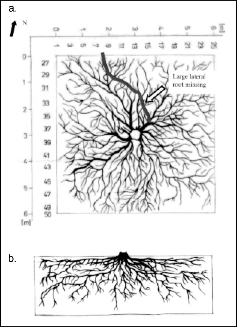
The GPR images, drawn by hand from the data, suggested that the pine root system occupied practically all the area examined and that roots extended farther than the studied transects, which is in agreement with observations when the root system was excavated (Figures 3a and 4a). The data illustrated that the trunk was positioned centrally within the root system, which was itself circular in shape. As the roots were excavated to a depth of 0.5 to 1 m (1.6 to 3.3 ft), it could be seen that the root system consisted of two tiers, with most lateral roots in the top 20 cm (7.9 in.) of soil. Between a depth of 20 and 80 cm (31.5 in.), no lateral roots > 2 cm (0.8 in.) in diameter were found (Figure 3b). When the GPR images of the pine root system in the vertical plane (Figure 4b) were compared with field observations (Figure 3b), no similarities in root architecture were found.

(a) Photograph of an excavated Pinus nigra root system in the horizontal plane and (b) a schematic illustration of the root system in the vertical plane. A photograph is not available due to the difficulty in obtaining a clear photograph in this plane. The schematic illustration shows that lateral roots were abundant in the top 20 cm (7.9 in.) of soil, and then again at a depth of 80 cm (31.4 in.). Between these two distances, no lateral roots were found; however, vertical roots were present.

(a) Ground plan view of the Pinus nigra root system, redrawn from the ground-penetrating radar data. One major lateral root has not been detected by the GPR system. (b) Vertical view of the same root system drawn to the same scale. The GPR image of roots in the vertical plane (b) suggests that lateral roots were present at depths of 0 to 100 cm (0 to 39.3 in.); however, this was not the case in reality (Figure 3b).
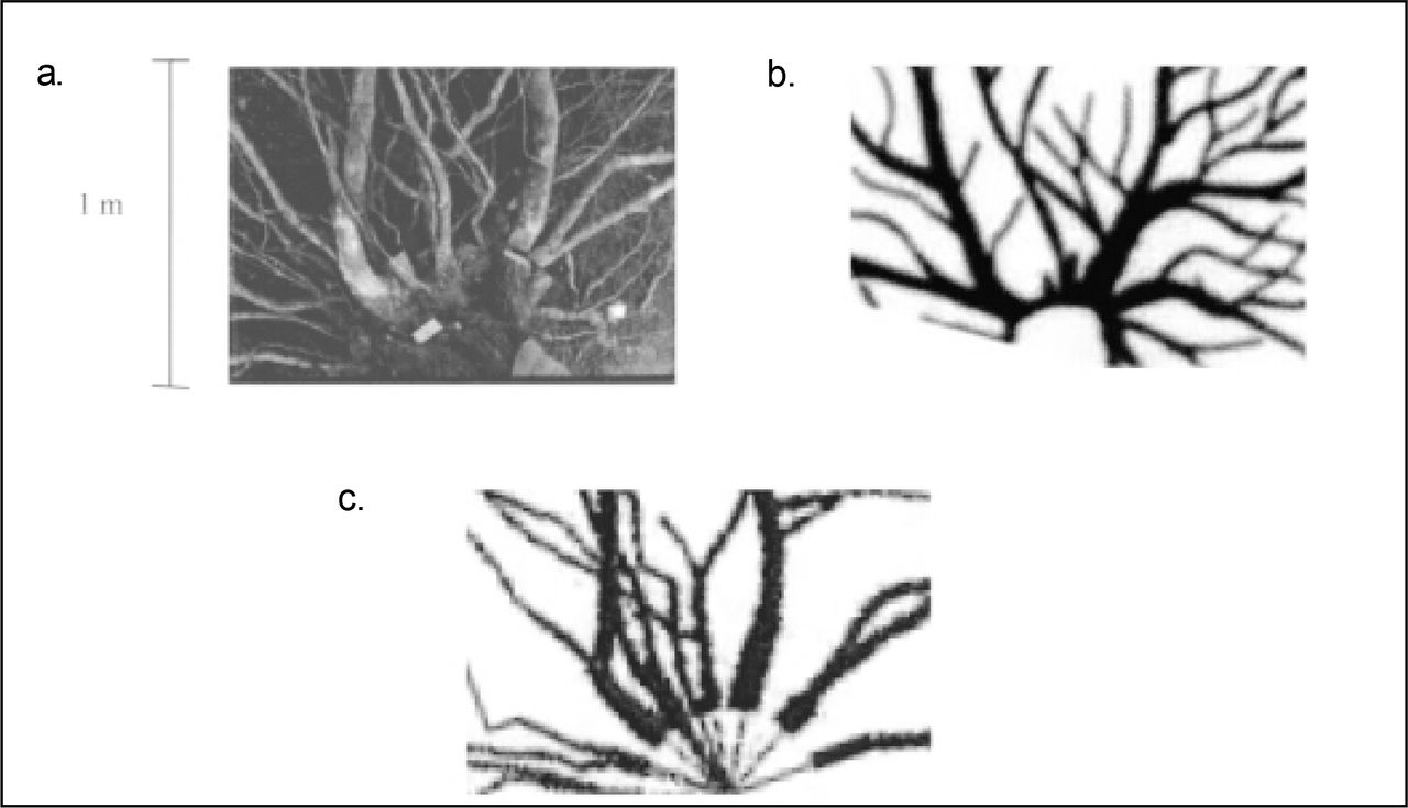
The image of the pine root system reconstructed by AMAPmod (Figure 5) was compared to that obtained by GPR (Figure 4a). Two-dimensional images of the root system in the horizontal plane only were compared (Figures 6a, 6b, and 6c). A reasonable likeness existed between the images with regard to the large lateral roots, except for the absence of one major lateral root that had not been captured on the GPR image (Figure 4a). However, many smaller roots existed on the GPR image that were not present on the image of the reconstructed root system and vice versa. These smaller roots on the GPR image may have been roots growing deeper than 20 cm (7.9 in.), which are not discriminated against in the horizontal plane. It was unlikely that these objects were building rubble such as cables and pipes, because such objects were found and mapped during the root system excavation, yet were not perceived in the GPR root system images. It may be possible that stones were mistaken for roots, but also unlikely, because stones can be discriminated against due to their shape and density. It was, however, impossible to obtain the true root system architecture from the GPR data because GPR was unable to distinguish from crossing-over of roots and branching. Very few second- and third-order lateral roots were present in the horizontal plane (i.e., there was little branching), yet the GPR data suggest that a high amount of branching was present in the pine root system.

Two-dimensional reconstruction of the Pinus nigra root system (only the northern half of the root system shown) derived from manually digitized architecture data and redrawn using AMAPmod software.

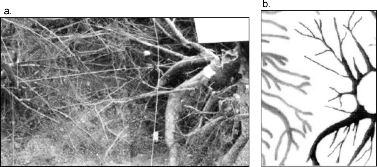
Comparison of one 1 m2 (10.8 ft2) transect from the root system of Pinus nigra, using images from (a) photograph, (b) GPR data, and (c) 2D reconstruction derived from digitized architecture data. The large lateral roots appear to be detected by GPR, as can be seen from both the photograph and the 2D digitized image.
The root systems of both mountain ash trees were also mapped using the GPR technique (Figure 7), and although the root systems were excavated, they were not digitized due to lack of time. However, from the photographs taken of each transect, it can again be seen that large roots are identifiable using GPR, but that smaller root position and root architecture is not accurate (Figures 8a and 8b). Root density appeared to be much higher in both mountain ash trees compared to the pine tree, especially with regard to roots < 2 cm (0.08 in.) in diameter. The root systems of both trees did not overlap, nor did roots of the two trees fuse, which was clear from both the GPR images and the photographs, as well as field observations (Figures 8a and 8b).

Ground plan view of both Sorbus intermedia root systems, redrawn from the ground-penetrating radar data. The GPR image suggests that root systems do not overlap or fuse with each other.

(a) Photograph of two transects taken from near the trunk of one Sorbus intermedia root system. The large lateral roots can be identified in (b), the image redrawn from the GPR data, as well as the lack of roots and root fusion between the two neighboring root systems.
DISCUSSION
The GPR technique was relatively easy and rapid to use in the field, provided that an experienced user manipulates the portable radar device and analyzes the data. Data evaluation takes a considerably longer time. Potential interference from building rubble, pipes, and cables could be distinguished from the tree roots because these objects were found and noted during the excavation but were not included in the analysis of GPR data. Aside from the inevitable errors produced by manually redrawing root systems (Sustek et al. 1999), several problems exist with the technique and, in the horizontal plane, are concerned with the accuracy of root size and root system architecture. Although large roots could easily be identified using GPR, smaller roots [< 20 mm (0.8 in.) in diameter] could not, nor could the GPR distinguish between root branching and two roots crossing over each other. More thin roots were seen to be connected to the main root system in the GPR images of pine than was actually the case. However, when the roots were digitized, only lateral roots and their daughter branches could be analyzed with AMAPmod; therefore, much information was lost. Extra roots may appear in the GPR images because data analysis is unable to discriminate against roots at a certain depth; therefore, all roots between 20 and 100 cm (7.8 and 39.3 in.) were present in the images of roots in the horizontal plane.
The GPR technique failed to provide useful information when data in the vertical plane were analyzed. GPR images in the vertical plane did not correspond at all to photographs and field observations taken for the pine tree. Although mountain ash root systems were not fully excavated, it can be assumed that GPR data were not accurate for these roots either. The problem with the technique in the vertical plane is that the radar signal cannot identify objects running parallel to the electromagnetic waves transmitted.
It may be possible to use GPR as a tool for tree diagnostics, with the possibility even of determining the healthiness of roots, by quantifying their internal water content, as suggested by Hruska et al. (1999). However, much more research and calibrating of species with root health would be needed. As a first step, software should be created that could model root system architecture using GPR data. This software could consider the laws governing tree root architecture, structure, and function for a given species type (e.g., conifer or broadleaf) and could be used to reconstruct the root system instead of it having to be redrawn by hand from the data (Jourdan and Rey 1997; Blaise et al. 2000). A candidate for such software is AMAPmod, which is used to reconstruct 3D images from raw data. AMAPmod is simple to use and not only provides 3D images, but it can be used to analyze data using statistical functions. Other techniques as well may be used in conjunction with such a software; for example, a stereological procedure has recently been used to nondestructively estimate root architecture of the grass Agropyron cristatum, which had been grown in a transparent medium (Wulfsohn et al. 1999).
The GPR technique is not cheap, but it may be worthwhile to use on valuable trees or trees in delicate situations where excavation is not possible, such as trees growing near pavements, roads, buildings, on unstable slopes, and possibly also in rapid tree screening schemes. Further development of this technique is possible, and huge advances in the software could be made in order to process root architecture data faster and more accurately. With such software and better object resolution, GPR could one day be considered as a useful, nondestructive, rapid technique for assessing root position, root system architecture, and in the long term, root health.
Acknowledgments
This study was funded by the John Z. Duling Grant Program (International Society of Arboriculture).
- © 2002, International Society of Arboriculture. All rights reserved.
In this issue


Jump to section
Related Articles
Cited By...
- No citing articles found.